Transformers are an essential part of electric distribution. Their role is to either increase or decrease the voltage that passes to individual buildings from the power plants. They have proven to be one of the most efficient electrical devices with an efficiency rating that is above 97%.
Do keep in mind that no matter the load, the transformers will stay operational and will definitely save thousands of dollars in the long run.
What are Transformers
An electrical transformer is basically an electromagnetic device. It works by converting the electrical energy of a single circuit to some other one. It does so without changing the power or the frequency of the electrical energy.
Their main goal is to increase the efficiency as well as the safety of the electric power systems by lowering or raising the overall voltage levels when it is required. By using a new transformer, you will be increasing the efficiency of your system and in turn saving electricity usage.
With the use of some semiconductor devices, a transformer can create direct current signals also, but without them, it can only alter the signal on the input.
The Working Principle behind Transformers
The working principle behind transformers is electromagnetic induction. It means that a conductor that carries the current produces a magnetic field and the same is applied the other way around. The transformer consists of two different wire sets.
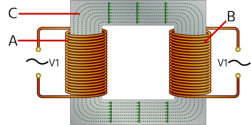
· The Primary winding (A) that collects power
· The Secondary winding (B) that provides power

Primary windings (A) and secondary windings (B) of a transformer wound on a magnetic core(C)
As seen in Figure 2, both primary and secondary windings are wounded on a magnetic iron circuit core. However, the coils do not have any contact between them. The core itself is produced from a material that is soft and magnetic and that consists of laminations.
It is linked together in order to help with the reduction of core loss which is energy that is lost inside the core due to altering magnetic flux. The core material’s functioning will be destroyed eventually if the magnetic field is unstable.
Upon connecting a primary winding to a power supply that is alternating, the current start to flow throughout the coil resulting in magnetic flux being induced. The secondary winding is linked with a portion of this magnetic field through mutual induction.
This as a result, at the secondary (load) side, produces a current flow and voltage. The load side voltage is equal to the number of turns in the secondary winding which is also relative to the primary side.
The Construction of the Transformer
There are two basic transformer construction designs. It depends on the windings and how they are wound together around the core. There is a core type which has both primary and secondary coils wound on the core ring on the outside surrounding it. On the other hand, a shell type forms a shell around the windings where the windings do not go around the core but on the inside.
Core Types
Core-type transformers are built where half of both primary and secondary windings are placed over one another on both legs of the magnetic circuit. This way the magnetic coupling is increased. This way magnetic lines of force are allowed to pass each of the windings at the same time.
That being said, there are some magnetic lines of force that flow outside due to the construction of the transformer. There are different layers of the coils that are cylindrical and they are insulated from each other. The most common materials used for insulation are cloth, mica, or paper. Low-voltage windings, which are much easier to insulate, are placed next to the core.
Shell Types
In these types of transformers, both secondary and primary coils are stacked and wound together with added insulation between them. Here, both windings are wounded together on the same leg. This way it has a cross-sectional area which is twice as big compared to the area of the two outer limbs. This type of transformer is more efficient as it has less core losses in general.
Transformer Core Types
Depending on how the lamination stampings are connected with each other, determines the overall required shape of the core. The goal in production is to create a highly saturated magnetic flux density. This is achieved by tightly placing laminations together when they are in the construction process. The air gap needs to be as small as possible.
Application of Different Transformers
Different types of transformers have different applications. Step-down transformers are the ones that are used in inverters, home appliances, transmission lines, and power distribution networks with the goal of lowering the voltage.
Step-up transformers have the purpose of distributing electricity. They are used for x-ray machines, microwaves, and electric motors in general. Instrument transformers are comparable to both voltage and current transformers.
They are used in cases of extremely high voltages in order to measure it. Single-phase transformers are used in light-commercial as well as residential devices in order to step-down signals over a long distance or to step-up power for home inverters.
Lastly, three-phase transformers are most commonly used in industries that use high-power equipment like rectifiers and motor drives.


1 Comment
A transformer converts voltage. No current flows until the transformer is connected to a load. Nothing but a potential is created. Just like a battery no current flows until a load is connected. Also transformers are never completely efficient and there is always power loses. Never a power gain. Put in 100 watts in and only get 98 watts out. The benefit are in higher voltages which can be transmitted with fewer losses.